CatlikeCoding
CatlikeCoding
Basics
Shader Fundamentals
float4 position : SV_POSITION; is transformed position after interpolation from float4 position : POSITION;
so we need one more value (eg. uv) stands for the local position
1
2
3
4
i.uv = TRANSFORM_TEX(v.uv, _MainTex);
i.uv = v.uv * _MainTex_ST.xy + _MainTex_ST.zw;
// equivalent
// used for tilling and offest
1
2
3
4
5
            struct VertexData {
                float4 position : POSITION;
                float2 uv : TEXCOORD0;
            };
// uv here is the uv from the mesh
Combine Texture
1
2
3
4
5
6
7
8
9
10
11
12
13
14
15
16
17
18
19
20
21
22
23
24
25
26
27
28
29
30
31
32
33
34
35
36
37
38
39
40
41
42
43
44
45
46
47
48
49
50
51
52
53
54
55
56
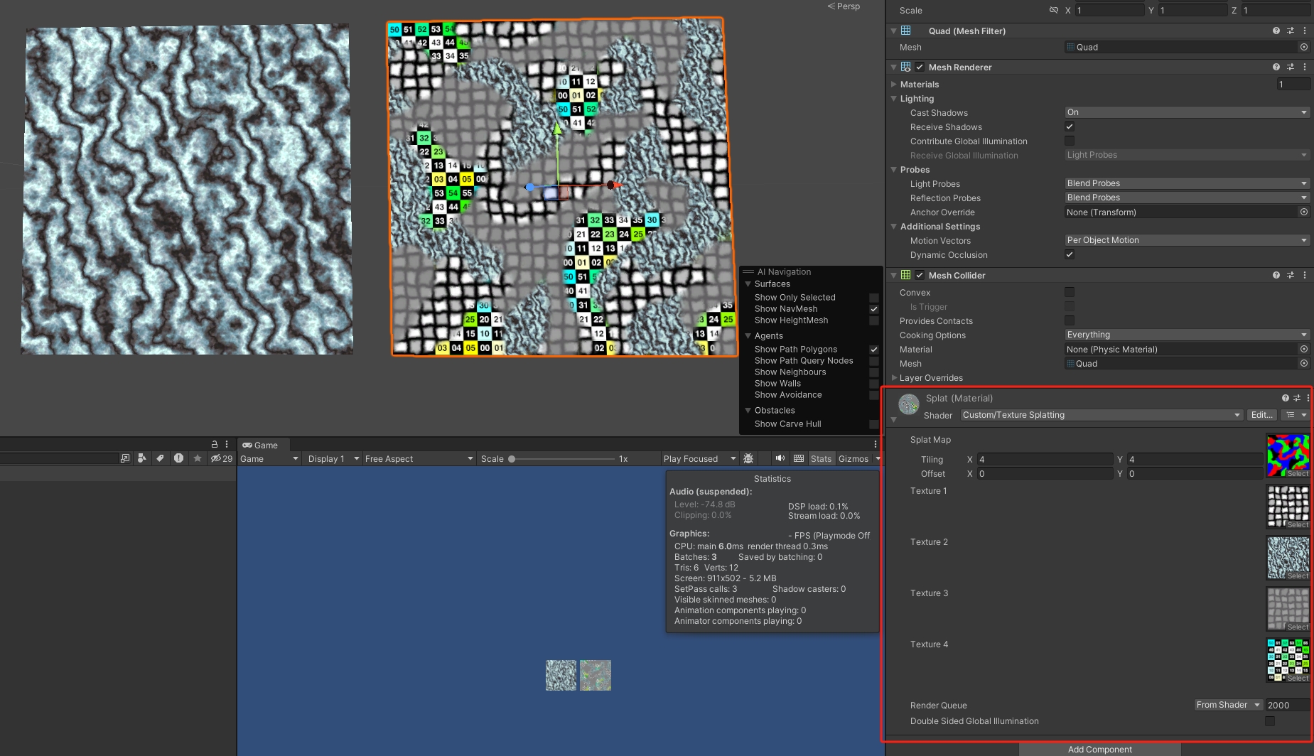
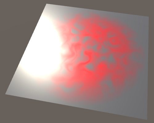
Shader "Custom/Texture Splatting" {
Properties {
_MainTex ("Splat Map", 2D) = "white" {}
[NoScaleOffset] _Texture1 ("Texture 1", 2D) = "white" {}
[NoScaleOffset] _Texture2 ("Texture 2", 2D) = "white" {}
[NoScaleOffset] _Texture3 ("Texture 3", 2D) = "white" {}
[NoScaleOffset] _Texture4 ("Texture 4", 2D) = "white" {}
}
SubShader {
Pass {
CGPROGRAM
#pragma vertex MyVertexProgram
#pragma fragment MyFragmentProgram
#include "UnityCG.cginc"
sampler2D _MainTex;
float4 _MainTex_ST;
sampler2D _Texture1, _Texture2, _Texture3, _Texture4;
struct VertexData {
float4 position : POSITION;
float2 uv : TEXCOORD0;
};
struct Interpolators {
float4 position : SV_POSITION;
float2 uv : TEXCOORD0;
float2 uvSplat : TEXCOORD1;
};
Interpolators MyVertexProgram (VertexData v) {
Interpolators i;
i.position = UnityObjectToClipPos(v.position);
i.uv = TRANSFORM_TEX(v.uv, _MainTex);
i.uvSplat = v.uv;
return i;
}
float4 MyFragmentProgram (Interpolators i) : SV_TARGET {
float4 splat = tex2D(_MainTex, i.uvSplat);
return
tex2D(_Texture1, i.uv) * splat.r +
tex2D(_Texture2, i.uv) * splat.g +
tex2D(_Texture3, i.uv) * splat.b +
tex2D(_Texture4, i.uv) * (1 - splat.r - splat.g - splat.b);
}
ENDCG
}
}
}
Light
Diffuse
#include "UnityStandardBRDF.cginc": defines the convenient DotClamped function, It contains a lot of other lighting function
float4 _WorldSpaceLightPos0: It has four components, because these are homogeneous coordinates. So the fourth component is 0 for our directional light.
fixed4 _LightColor0: This variable contains the light’s color, multiplied by its intensity. Although it provides all four channels, we only need the RGB components.
1
2
3
4
5
6
7
8
9
10
11
12
13
14
Tags {
    "LightMode" = "ForwardBase"
}
.

float4 MyFragmentProgram (Interpolators i) : SV_TARGET {
    i.normal = normalize(i.normal);
    float3 lightDir = _WorldSpaceLightPos0.xyz;
    float3 lightColor = _LightColor0.rgb;
    float3 albedo = tex2D(_MainTex, i.uv).rgb * _Tint.rgb;
    float3 diffuse =
        albedo * lightColor * DotClamped(lightDir, i.normal);
    return float4(diffuse, 1);
}
Specular
float3 _WorldSpaceCameraPos: The position of the camera can be accessed
unity_ObjectToWorld: object-to-world matrix
reflect: It takes the direction of an incoming light ray and reflects it based on a surface normal.
1
2

                float3 reflectionDir = reflect(-lightDir, i.normal);
Blinn-Phong: It uses a vector halfway between the light direction and the view direction. The dot product between the normal and the half vector determines the specular contribution.
1
2
3
4
5
6
7
8
9
10
11
12
13
14
			float4 MyFragmentProgram (Interpolators i) : SV_TARGET {
				i.normal = normalize(i.normal);
				float3 lightDir = _WorldSpaceLightPos0.xyz;
                float3 viewDir = normalize(_WorldSpaceCameraPos - i.worldPos);
				float3 lightColor = _LightColor0.rgb;
				float3 albedo = tex2D(_MainTex, i.uv).rgb * _Tint.rgb;
				float3 diffuse =
					albedo * lightColor * DotClamped(lightDir, i.normal);
                float3 halfVector = normalize(lightDir + viewDir);

				return pow(
					DotClamped(halfVector, i.normal),
					_Smoothness * 100
				);
Energy Conservation
EnergyConservationBetweenDiffuseAndSpecular: utility function to take care of the energy conservation
(too bright, need to be absorbed)
1
2
3
4
5
6
7
8
9
10
11
12
13
14
15
16
17
18
19
20
21
22
23
24
                #include "UnityStandardUtils.cginc"

			float4 MyFragmentProgram (Interpolators i) : SV_TARGET {
				i.normal = normalize(i.normal);
				float3 lightDir = _WorldSpaceLightPos0.xyz;
                float3 viewDir = normalize(_WorldSpaceCameraPos - i.worldPos);
				float3 lightColor = _LightColor0.rgb;
				float3 albedo = tex2D(_MainTex, i.uv).rgb * _Tint.rgb;
                float oneMinusReflectivity;
				albedo = EnergyConservationBetweenDiffuseAndSpecular(
					albedo, _SpecularTint.rgb, oneMinusReflectivity
				);
				float3 diffuse =
					albedo * lightColor * DotClamped(lightDir, i.normal);
                float3 halfVector = normalize(lightDir + viewDir);
                float3 specular = _SpecularTint.rgb * lightColor * pow(
					DotClamped(halfVector, i.normal),
					_Smoothness * 100
				);

				return float4(diffuse + specular, 1);
			}
            ENDCG
        }
metals: strong specular tint, monochrome, do not have albedo
nonmetals / dielectric: weak monochrome specular, don’t have a colored specular
DiffuseAndSpecularFromMetallic: Even pure dielectrics still have some specular reflection. UnityStandardUtils also has the DiffuseAndSpecularFromMetallic function, which takes care of this for us.
1
2
3
4
5
6
7
8
9
10
11
12
13
14
15
16
17
18
19
20
21
			float4 MyFragmentProgram (Interpolators i) : SV_TARGET {
				i.normal = normalize(i.normal);
				float3 lightDir = _WorldSpaceLightPos0.xyz;
                float3 viewDir = normalize(_WorldSpaceCameraPos - i.worldPos);
				float3 lightColor = _LightColor0.rgb;
				float3 albedo = tex2D(_MainTex, i.uv).rgb * _Tint.rgb;
                float3 specularTint;
				float oneMinusReflectivity;
				albedo = DiffuseAndSpecularFromMetallic(
					albedo, _Metallic, specularTint, oneMinusReflectivity
				);
				float3 diffuse =
					albedo * lightColor * DotClamped(lightDir, i.normal);
                float3 halfVector = normalize(lightDir + viewDir);
                float3 specular = specularTint * lightColor * pow(
					DotClamped(halfVector, i.normal),
					_Smoothness * 100
				);

				return float4(diffuse + specular, 1);
			}
Physically-Based Shading
#pragma target 3.0: To make sure that Unity selects the best BRDF function, we have to target at least shader level 3.0
BRDF: stands for bidirectional reflectance distribution function.
UNITY_BRDF_PBS: The algorithm is accessible via the **UNITY_BRDF_PBS** macro, which is defined in UnityPBSLighting, The functions each have eight parameters.
1
2
3
4
5
6
7
8
9
10
11
12
13
14
15
16
17
18
19
20
21
22
23
24
25
26
27
28
29
			float4 MyFragmentProgram (Interpolators i) : SV_TARGET {
				i.normal = normalize(i.normal);
				float3 lightDir = _WorldSpaceLightPos0.xyz;
				float3 viewDir = normalize(_WorldSpaceCameraPos - i.worldPos);

				float3 lightColor = _LightColor0.rgb;
				float3 albedo = tex2D(_MainTex, i.uv).rgb * _Tint.rgb;

				float3 specularTint;
				float oneMinusReflectivity;
				albedo = DiffuseAndSpecularFromMetallic(
					albedo, _Metallic, specularTint, oneMinusReflectivity
				);

				UnityLight light;
				light.color = lightColor;
				light.dir = lightDir;
				light.ndotl = DotClamped(i.normal, lightDir);
				UnityIndirect indirectLight;
				indirectLight.diffuse = 0;
				indirectLight.specular = 0;

				return UNITY_BRDF_PBS(
					albedo, specularTint,
					oneMinusReflectivity, _Smoothness,
					i.normal, viewDir,
					light, indirectLight
				);
			}
Multiple Lights
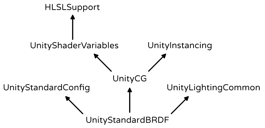
Include Files
1
2
3
4
5
6
7
8
#if !defined(MY_LIGHTING_INCLUDED)
#define MY_LIGHTING_INCLUDED

#include "UnityPBSLighting.cginc"

…

#endif
Second Light
Blend One One: The default mode is no blending, which is equivalent to One Zero. The result of such a pass replaced anything that was previously in the frame buffer. To add to the frame buffer, we’ll have to instruct it to use the One One blend mode. This is known as additive blending.
1
2
3
4
5
6
7
8
9
10
11
12
13
14
15
16
17
18
19
        Pass {
			Tags {
				"LightMode" = "ForwardAdd"
			}

            Blend One One
            ZWrite Off

			CGPROGRAM

			#pragma target 3.0

			#pragma vertex MyVertexProgram
			#pragma fragment MyFragmentProgram

			#include "MyLighting.cginc"

			ENDCG
		}
Point Light
The _WorldSpaceLightPos0 variable contains the current light’s position.
But in case of a directional light, it actually holds the direction towards the light.
This is done by subtracting the fragment’s world position and normalizing the result.
1
light.dir = normalize(_WorldSpaceLightPos0.xyz - i.worldPos);
UNITY_LIGHT_ATTENUATION
#define POINT: there are multiple versions of it, one per light type. By default, it’s for the directional light, which has no attenuation at all.
1
2
3
4
5
6
7
8
9
10
11
12
13
14
15
16
17
18
19
20
21
22
23
24
25
26
27
28
29
30
31
        Pass {
			Tags {
				"LightMode" = "ForwardAdd"
			}

            Blend One One
            ZWrite Off

			CGPROGRAM

			#pragma target 3.0

			#pragma vertex MyVertexProgram
			#pragma fragment MyFragmentProgram

            #define POINT

			#include "MyLighting.cginc"

			ENDCG
		}
    }

UnityLight CreateLight (Interpolators i) {
    UnityLight light;
    light.dir = normalize(_WorldSpaceLightPos0.xyz - i.worldPos);
    UNITY_LIGHT_ATTENUATION(attenuation, 0, i.worldPos);
    light.color = _LightColor0.rgb * attenuation;
    light.ndotl = DotClamped(i.normal, light.dir);
    return light;
}
Mixing Light
Shader Variants
#pragma multi_compile DIRECTIONAL POINT: This statement defines a list of keywords. Unity will create multiple shader variants for us, each defining one of those keywords.
Unity decides which variant to use based on the current light and the shader variant keywords. When rendering a directional light, it uses the DIRECTIONAl variant. When rendering a point light, it uses the POINT variant. And when there isn’t a match, it just picks the first variant from the list.
1
2
3
4
5
6
7
8
9
10
11
12
13
14
15
            UnityLight CreateLight (Interpolators i) {
                UnityLight light;

                #if defined(POINT)
                    light.dir = normalize(_WorldSpaceLightPos0.xyz - i.worldPos);
                #else
                    light.dir = _WorldSpaceLightPos0.xyz;
                #endif

                float3 lightVec = _WorldSpaceLightPos0.xyz - i.worldPos;
                UNITY_LIGHT_ATTENUATION(attenuation, 0, i.worldPos);
                light.color = _LightColor0.rgb * attenuation;
                light.ndotl = DotClamped(i.normal, light.dir);
                return light;
            }
Vertex Lights
Every visible object always gets rendered with its base pass. This pass takes care of the main directional light. Every additional light will add an extra additive pass on top of that. Thus, many lights will result in many draw calls.
The problem is so bad, because lights are completely switched off. Fortunately, there is another way to render lights much cheaper, without completely turning them off. We can render them per vertex, instead of per fragment.
Vertex lighting is only supported for point lights.
unity_LightColor[0].rgb: UnityShaderVariables defines an array of vertex light colors.
Spherical Harmonics
ShadeSH9: UnityCG contains the ShadeSH9 function, which computes lighting based on the spherical harmonics data, and a normal parameter.
https://catlikecoding.com/unity/tutorials/rendering/part-5/
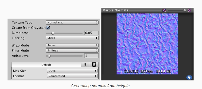
Bumpiness
Height map
how to process height map -> normal
1
2
[NoScaleOffset] _HeightMap ("Heights", 2D) = "gray" {}
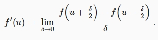
Central Difference: We’ve used finite difference approximations to create normal vectors. Specifically, by using the forward difference method. We take a point, and then look in one direction to determine the slope. As a result, the normal is biased in that direction. To get a better approximation of the normal, we can instead offset the sample points in both directions. This centers the linear approximation on the current point, and is known as the central difference method.
1
2
3
4
5
6
7
            void InitializeFragmentNormal(inout Interpolators i) {
                float2 delta = float2(_HeightMap_TexelSize.x * 0.5, 0);
                float h1 = tex2D(_HeightMap, i.uv - delta);
                float h2 = tex2D(_HeightMap, i.uv + delta);
                i.normal = float3(h1 - h2, 1, 0);
                i.normal = normalize(i.normal);
            }
Using Both Dimensions ->cross product \({ {A}\times{B}={\left|{\left|{A}\right|}\right|}{\left|{\left|{B}\right|}\right|} \sin{N} }\)
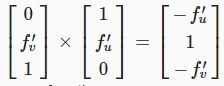
we can construct the vector directly, instead of having to rely on the cross function.
1
2
3
4
5
6
7
8
9
10
11
12
            void InitializeFragmentNormal(inout Interpolators i) {
                float2 du = float2(_HeightMap_TexelSize.x * 0.5, 0);
                float u1 = tex2D(_HeightMap, i.uv - du);
                float u2 = tex2D(_HeightMap, i.uv + du);

                float2 dv = float2(0, _HeightMap_TexelSize.y * 0.5);
                float v1 = tex2D(_HeightMap, i.uv - dv);
                float v2 = tex2D(_HeightMap, i.uv + dv);

                i.normal = float3(u1 - u2, 1, v1 - v2);
                i.normal = normalize(i.normal);
            }
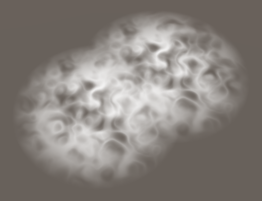
Normal Mapping
Grey Scale -> RGB normal map -> save calculation
While bump mapping works, we have to perform multiple texture samples and finite difference calculations. This seems like a waste, as the resulting normal should always be the same. Why do all this work every frame? We can do it once and store the normals in a texture.
1
2
3
4
5
6
7
8
[NoScaleOffset] _NormalMap ("Normals", 2D) = "bump" {}
…
sampler2D _NormalMap;
…
void InitializeFragmentNormal(inout Interpolators i) {
	i.normal = tex2D(_NormalMap, i.uv).rgb;
	i.normal = normalize(i.normal);
}
DXT5nm: Even though the texture preview shows RGB encoding, Unity actually uses DXT5nm. The DXT5nm format only stores the X and Y components of the normal. Its Z component is discarded. The Y component is stored in the G channel, as you might expect. However, the X component is stored in the A channel. The R and B channels are not used.
1
2
3
4
5
            void InitializeFragmentNormal(inout Interpolators i) {
                i.normal.xy = tex2D(_NormalMap, i.uv).wy * 2 - 1;
                i.normal.z = sqrt(1 - saturate(dot(i.normal.xy, i.normal.xy)));
                i.normal = i.normal.xzy;
            }
UnpackScaleNormal: UnityStandardUtils contains the UnpackScaleNormal function. It automatically uses the correct decoding for normal maps, and scales normals as well.
1
2
3
4
5
6
7
8
void InitializeFragmentNormal(inout Interpolators i) {
//	i.normal.xy = tex2D(_NormalMap, i.uv).wy * 2 - 1;
//	i.normal.xy *= _BumpScale;
//	i.normal.z = sqrt(1 - saturate(dot(i.normal.xy, i.normal.xy)));
	i.normal = UnpackScaleNormal(tex2D(_NormalMap, i.uv), _BumpScale);
	i.normal = i.normal.xzy;
	i.normal = normalize(i.normal);
}
Bump Details
detail map + mainTex
More details on How to blend Normal
BlendNormals: UnityStandardUtils contains the BlendNormals function, which also uses whiteout blending.
1
2
3
4
5
6
7
8
            void InitializeFragmentNormal(inout Interpolators i) {
                float3 mainNormal =
                    UnpackScaleNormal(tex2D(_NormalMap, i.uv.xy), _BumpScale);
                float3 detailNormal =
                    UnpackScaleNormal(tex2D(_DetailNormalMap, i.uv.zw), _DetailBumpScale);
                i.normal = BlendNormals(mainNormal, detailNormal);
                i.normal = i.normal.xzy;
            }
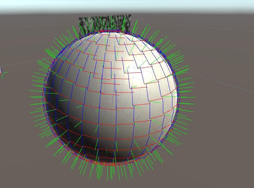
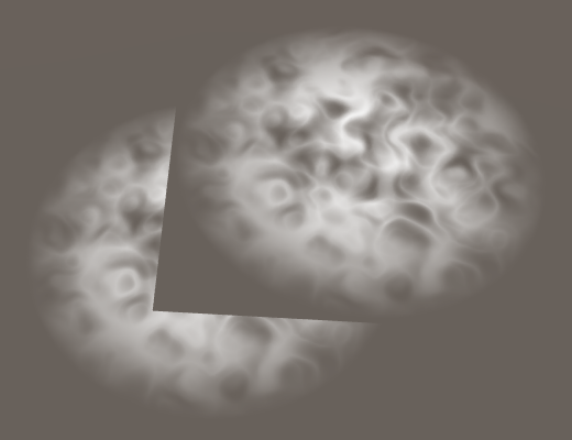
Tangent Space
Up to this points, we have assumed that we’re shading a flat surface that is aligned with the XZ plane. But for this technique to be of any use, it must work for arbitrary geometry.
We can use the vertex normal and tangent to construct a 3D space that matches the mesh surface. This space is known as tangent space, the tangent basis, or TBN space. In the case of a cube, tangent space is uniform per face. In the case of a sphere, tangent space wraps around its surface. \({ B={N \times T} }\)
1
2
3
4
5
6
7
8
9
10
11
12
13
14
            Interpolators MyVertexProgram (VertexData v) {
                Interpolators i;
                i.position = UnityObjectToClipPos(v.position);
                i.worldPos = mul(unity_ObjectToWorld, v.position);

                i.normal = UnityObjectToWorldNormal(v.normal);
                //to world space
                i.tangent = float4(UnityObjectToWorldDir(v.tangent.xyz), v.tangent.w);

                i.uv.xy = TRANSFORM_TEX(v.uv, _MainTex);
	            i.uv.zw = TRANSFORM_TEX(v.uv, _DetailTex);
                ComputeVertexLightColor(i);
                return i;
            }
1
2
3
4
5
6
7
8
9
10
11
12
13
14
15
            void InitializeFragmentNormal(inout Interpolators i) {
                float3 mainNormal =
                    UnpackScaleNormal(tex2D(_NormalMap, i.uv.xy), _BumpScale);
                float3 detailNormal =
                    UnpackScaleNormal(tex2D(_DetailNormalMap, i.uv.zw), _DetailBumpScale);

                float3 tangentSpaceNormal = BlendNormals(mainNormal, detailNormal);
                float3 binormal = cross(i.normal, i.tangent.xyz) * i.tangent.w;

                i.normal = normalize(
                    tangentSpaceNormal.x * i.tangent +
                    tangentSpaceNormal.y * binormal +
                    tangentSpaceNormal.z * i.normal
                );
            }
If we want to be consistent with Unity’s standard shaders, we have to calculate the binormal per vertex. The upside of doing that is that we don’t have to compute a cross product in the fragment shader. The downside is that we need an additional interpolator. If you’re not sure which method to use, you can always support both.
Shadows
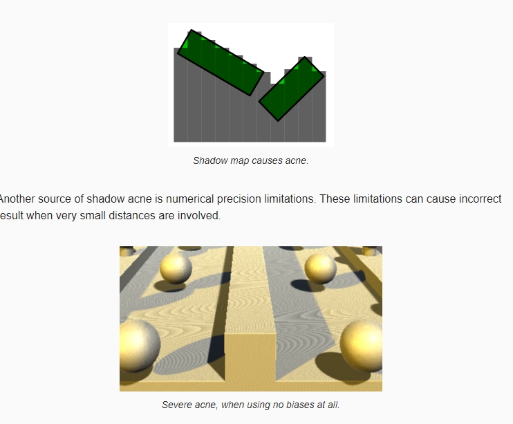
There are a few techniques to support real-time shadows. Each has it advantages and disadvantages. Unity uses the most common technique nowadays, which is shadow mapping.
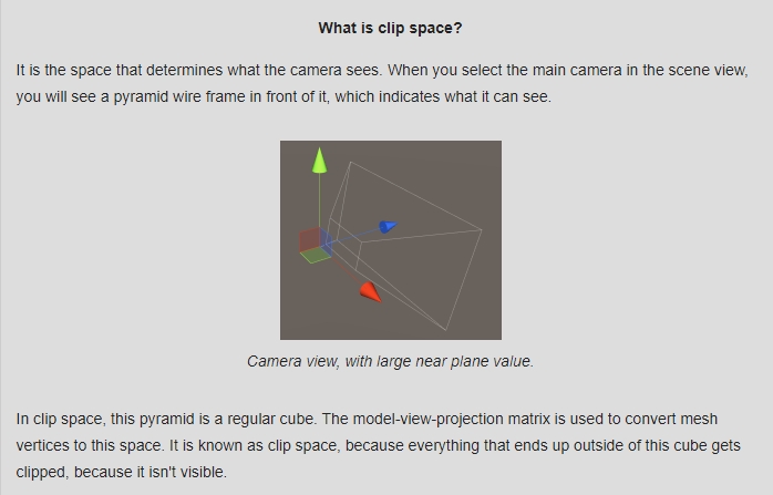
Collecting Shadows -> Shadow map : Conceptually, we have two vectors that should end up at the same point. If they do, both the camera and light can see that point, and so it is lit. If the light’s vector ends before reaching the point, then the light is blocked, which means that the point is shadowed.
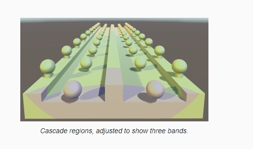
cascades: When you have a directional light casting shadows, it needs to cover a large area, such as an outdoor scene. However, rendering high-quality shadows across the entire scene can be computationally expensive. To address this, shadow cascades divide the camera frustum (the viewable area) into multiple cascades or regions with different levels of detail. Each cascade is then rendered with a different level of shadow map resolution.
The shape of the cascade bands depends on the Shadow Projection quality setting. The default is Stable Fit. In this mode, the bands are chosen based on the distance to the camera’s position. The other option is Close Fit, which uses the camera’s depth instead. This produces rectangular bands in the camera’s view direction.
Shadow swimming: the shadow projection now depends on the position and orientation or the camera. As a result, when the camera moves or rotates, the shadow maps change as well
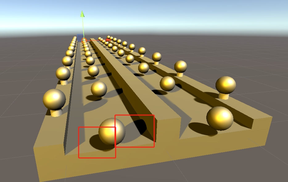
Shadow Acne: One way to prevent this problem is by adding a depth offset when rendering the shadow maps. This bias is added to the distance from the light to the shadow casting surface, pushes the shadows into the surfaces.
peter panning: But too large a bias can make it seem like shadows are disconnected from the objects that cast them. This effect is known as peter panning.
Normal Bias: This bias pushes the vertices of the shadow casters inwards, along their normals. This also reduces self-shadowing, but it also makes the shadows smaller and can cause holes to appear in the shadows.
MSAA: when Unity renders the screen-space shadow maps, it does so with a single quad that covers the entire view. As a result, there are no triangle edges, and thus MSAA does not affect the screen-space shadow map. MSAA does work for the final image, but the shadow values are taken straight from the screen-space shadow map. This becomes very obvious when a light surface next to a darker surface is shadowed. The edge between the light and dark geometry is anti-aliased, while the shadow edge isn’t.
Anti-aliasing methods that rely on image post-processing – like FXAA – don’t have this problem, because they are applied after the entire scene has been rendered.
Cast Shadow
We know that Unity renders the scene multiple times for directional shadows. Once for the depth pass, and once per light, for each shadow map cascade. The screen-space shadow map is a screen-space effect and doesn’t concern us.
To support all relevant passes, we have to add a pass to our shader, with its light mode set to ShadowCaster. Because we are only interested in the depth values, it will be a lot simpler than our other passes.
1
2
3
4
5
6
7
8
9
10
11
12
13
14
15
16
        Pass {
			Tags {
				"LightMode" = "ShadowCaster"
			}

			CGPROGRAM

			#pragma target 3.0

			#pragma vertex MyShadowVertexProgram
			#pragma fragment MyShadowFragmentProgram

			#include "My Shadows.cginc"

			ENDCG
		}
UnityClipSpaceShadowCasterPos: function to apply the normal bias.
To support the depth bias, we can use the UnityApplyLinearShadowBias function
1
2
3
4
5
6
7
8
9
10
11
12
13
14
15
16
17
18
19
20
#if !defined(MY_SHADOWS_INCLUDED)
#define MY_SHADOWS_INCLUDED

#include "UnityCG.cginc"

struct VertexData {
	float4 position : POSITION;
	float3 normal : NORMAL;
};

float4 MyShadowVertexProgram (VertexData v) : SV_POSITION {
	float4 position = UnityClipSpaceShadowCasterPos(v.position.xyz, v.normal);
	return UnityApplyLinearShadowBias(position);
}

half4 MyShadowFragmentProgram () : SV_TARGET {
	return 0;
}

#endif
Receive Shadow
When the main directional light casts shadows, Unity will look for a shader variant that has the SHADOWS_SCREEN keyword enabled. So we have to create two variants of our base pass, one with and one without this keyword. This works the same as for the VERTEXLIGHT_ON keyword.
The pass now has two multi-compile directives, each for a single keyword. As a result, there are four possible variants. One with no keywords, one for each keyword, and one with both keywords.
1
2
3
4
5
6
7
8
9
// Snippet #0 platforms ffffffff:
SHADOWS_SCREEN VERTEXLIGHT_ON

4 keyword variants used in scene:

<no keywords defined>
VERTEXLIGHT_ON
SHADOWS_SCREEN
SHADOWS_SCREEN VERTEXLIGHT_ON
1
2
3
4
5
6
7
8
9
10
11
12
13
14
15
16
17
18
19
20
21
		Pass {
			Tags {
				"LightMode" = "ForwardBase"
			}

			CGPROGRAM

			#pragma target 3.0

			#pragma multi_compile _ SHADOWS_SCREEN
			#pragma multi_compile _ VERTEXLIGHT_ON

			#pragma vertex MyVertexProgram
			#pragma fragment MyFragmentProgram

			#define FORWARD_BASE_PASS

			#include "MyLighting.cginc"

			ENDCG
		}
Sampling Shadows
To get to the shadows, we have to sample the screen-space shadow map.
Get screen-space texture coordinates
We can access the screen-space shadows via _ShadowMapTexture.
1
2
3
4
5
6
7
8
9
10
11
12
13
14
15
16
17
18
19
20
21
22
23
24
struct Interpolators {
	…

	#if defined(SHADOWS_SCREEN)
		float4 shadowCoordinates : TEXCOORD5;
	#endif

	#if defined(VERTEXLIGHT_ON)
		float3 vertexLightColor : TEXCOORD6;
	#endif
};

…

Interpolators MyVertexProgram (VertexData v) {
	…

	#if defined(SHADOWS_SCREEN)
		i.shadowCoordinates = i.position;
	#endif

	ComputeVertexLightColor(i);
	return i;
}
still on clip-space coordinates instead of screen-space coordinates
1
2
3
4
5
6
7
8
9
10
11
UnityLight CreateLight (Interpolators i) {
	…

	#if defined(SHADOWS_SCREEN)
		float attenuation = tex2D(_ShadowMapTexture, i.shadowCoordinates.xy);
	#else
		UNITY_LIGHT_ATTENUATION(attenuation, 0, i.worldPos);
	#endif

	…
}
we can use the ComputeScreenPos function from UnityCG
1
2
3
                #if defined(SHADOWS_SCREEN)
                    i.shadowCoordinates = ComputeScreenPos(i.position);
                #endif
SHADOW_COORDS defines the interpolator for shadow coordinates
1
2
3
4
5
6
7
8
9
10
struct Interpolators {
	…

//	#if defined(SHADOWS_SCREEN)
//		float4 shadowCoordinates : TEXCOORD5;
//	#endif
	SHADOW_COORDS(5)

	…
};
TRANSFER_SHADOW fills these coordinates in the vertex program.
1
2
3
4
5
6
7
8
9
10
Interpolators MyVertexProgram (VertexData v) {
	…

//	#if defined(SHADOWS_SCREEN)
//		i.shadowCoordinates = i.position;
//	#endif
	TRANSFER_SHADOW(i);

	…
}
Multiple Shadows
The main directional light is now casting shadows, but the second directional light still doesn’t. That’s because we don’t yet define SHADOWS_SCREEN in the additive pass. We could add a multi-compile statement to it, but SHADOWS_SCREEN only works for directional lights. To get the correct combination of keywords, change the existing multi-compile statement to one that also includes shadows.
1
#pragma multi_compile_fwdadd_fullshadows
Spot Light: there are big differences between a directional light and a spotlight. The spotlight has an actual position, and its light rays aren’t parallel. So the spotlight’s camera has a perspective view, and cannot be more around arbitrarily. As a result, these lights cannot support shadow cascades.
Point light: When you inspect the shadow maps via the frame debugger, you will discover that not one, but six maps are rendered per light. This happens because point lights shine in all directions. As as result, the shadow map has to be a cube map.
Just like with spotlight shadows, the shadow map is sampled once for hard shadows, and four times for soft shadows. The big difference is that Unity doesn’t support filtering for the shadow cube maps. As a result, the edges of the shadows are much harsher. So point light shadows are both expensive and aliased.
Reflection
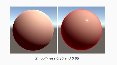
And apparently, it reflects more at its edge. That’s because every surface becomes more reflective as the view angle becomes more shallow. At glancing angles, most light is reflected, and everything becomes a mirror. This is known as Fresnel reflection.
The smoother a surface, the stronger the Fresnel reflections. When using a high smoothness, the red ring becomes very obvious.
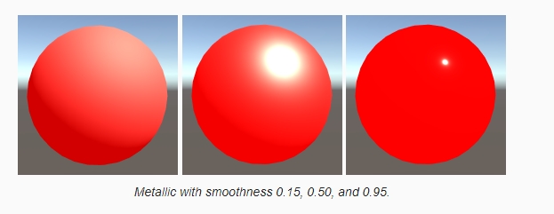
In the case of metals, the indirect reflections dominate everywhere. Instead of a black sphere, we now get a red one.
unity_SpecCube0: skybox cube map. It is defined as unity_SpecCube0 in UnityShaderVariables. The type of this variable depends on the target platform, which is determined in HSLSupport.
UNITY_SAMPLE_TEXCUBE: A cube map is sampled with a 3D vector, which specifies a sample direction.
1
2
3
4
5
6
7
8
9
10
11
12
13
14
15
16
17
UnityIndirect CreateIndirectLight (Interpolators i) {
	UnityIndirect indirectLight;
	indirectLight.diffuse = 0;
	indirectLight.specular = 0;

	#if defined(VERTEXLIGHT_ON)
		indirectLight.diffuse = i.vertexLightColor;
	#endif

	#if defined(FORWARD_BASE_PASS)
		indirectLight.diffuse += max(0, ShadeSH9(float4(i.normal, 1)));
		float3 envSample = UNITY_SAMPLE_TEXCUBE(unity_SpecCube0, i.normal);
		indirectLight.specular = envSample;
	#endif

	return indirectLight;
}
DecodeHDR: convert the samples from HDR format to RGB. The HDR data is stored in four channels, using the RGBM format. So we have to sample a float4 value, then convert.
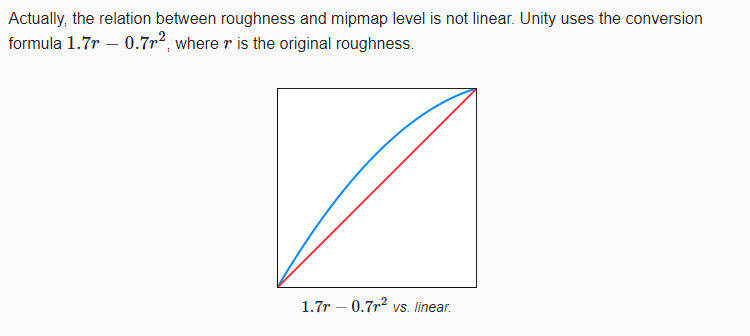
Imperfect Reflection
The rougher a surface becomes, the more diffuse its reflections get.
UNITY_SPECCUBE_LOD_STEPS: As roughness goes from 0 to 1, we have to scale it by the mipmap range that we’re using. Unity uses the UNITY_SPECCUBE_LOD_STEPS macro to determine this range, so let’s use it too.
UNITY_SAMPLE_TEXCUBE_LOD: We can use the **UNITY_SAMPLE_TEXCUBE_LOD** macro to sample a cube map at a specific mipmap level.
Unity_GlossyEnvironment: contains all the code to convert the roughness, sample the cube map, and convert from HDR
1
2
3
4
5
6
7
8
9
10
11
12
13
14
15
16
17
18
19
20
21
22
23
24
25
UnityIndirect CreateIndirectLight (Interpolators i, float3 viewDir) {
	UnityIndirect indirectLight;
	indirectLight.diffuse = 0;
	indirectLight.specular = 0;

	#if defined(VERTEXLIGHT_ON)
		indirectLight.diffuse = i.vertexLightColor;
	#endif

	#if defined(FORWARD_BASE_PASS)
		indirectLight.diffuse += max(0, ShadeSH9(float4(i.normal, 1)));
		float3 reflectionDir = reflect(-viewDir, i.normal);

		Unity_GlossyEnvironmentData envData;
		envData.roughness = 1 - _Smoothness;
		envData.reflUVW = reflectionDir;
		indirectLight.specular = Unity_GlossyEnvironment(
			UNITY_PASS_TEXCUBE(unity_SpecCube0), unity_SpecCube0_HDR, envData
		);


	#endif

	return indirectLight;
}
Bumpy Mirrors && Metals
Interpolating Probes
Unity supplies shaders with data of two reflection probes, so we can blend between them.
Use the UNITY_PASS_TEXCUBE_SAMPLER macro to combine the second probe’s texture with the only sampler that we have. that gets rid of the error.
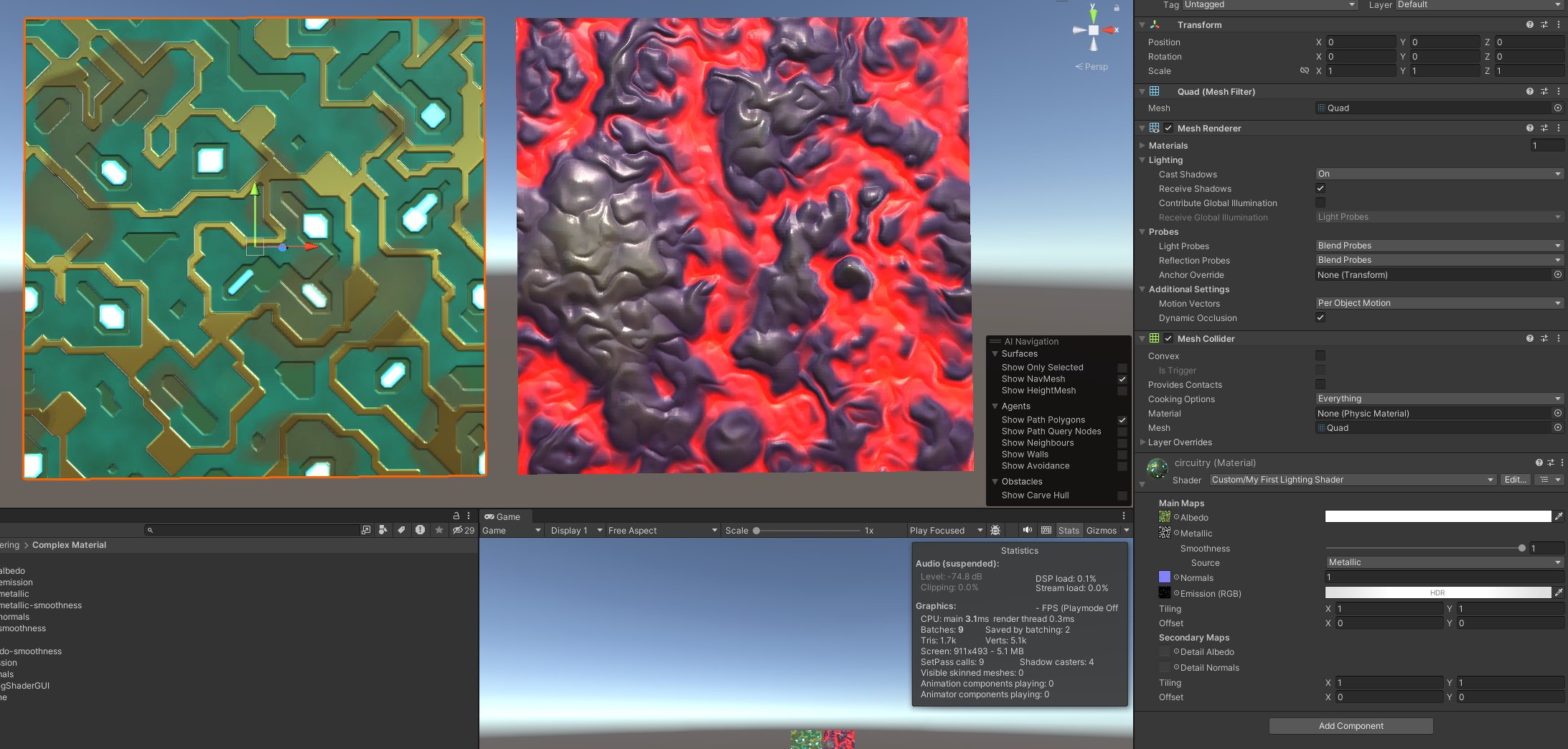
Complex Material
Shader GUI
1
	CustomEditor "MyLightingShaderGUI"
1
2
3
4
5
6
7
8
9
10
11
12
13
14
15
16
17
18
19
20
21
    void DoMain()
    {
        GUILayout.Label("Main Maps", EditorStyles.boldLabel);

        MaterialProperty mainTex = FindProperty("_MainTex");

        editor.TexturePropertySingleLine(
            MakeLabel(mainTex, "Albedo (RGB)"), mainTex, FindProperty("_Tint")
        );
        DoMetallic();
        DoSmoothness();
        DoNormals();
        editor.TextureScaleOffsetProperty(mainTex);
    }
    void DoMetallic()
    {
        MaterialProperty slider = FindProperty("_Metallic");
        EditorGUI.indentLevel += 2;
        editor.ShaderProperty(slider, MakeLabel(slider));
        EditorGUI.indentLevel -= 2;
    }
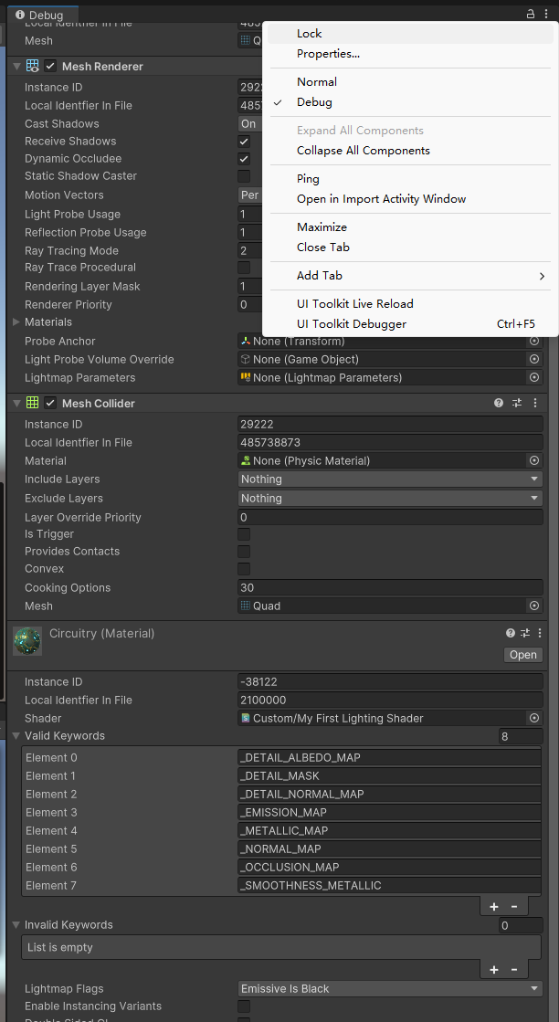
Metallic
Smoothness
Unity’s standard shader expects smoothness to be stored in the alpha channel.
For opaque materials that don’t require a metallic map, it is possible to store the smoothness in the alpha channel of the albedo map.
Emissive
- The emission is part of the material only. It doesn’t affect the rest of the scene. However, Unity’s global illumination system can pick up this emitted light and add it to the indirect illumination data.
Occluded Areas
1
2
3
4
5
6
7
float GetOcclusion (Interpolators i) {
	#if defined(_OCCLUSION_MAP)
		return lerp(1, tex2D(_OcclusionMap, i.uv.xy).g, _OcclusionStrength);
	#else
		return 1;
	#endif
}
- Ambient Light
- As the occlusion map is based on the surface shape and not on a specific light, it makes sense that it is only applied to indirect light.
- Having said that, you’ll often find games where occlusion maps are applied to direct lights as well. Unity’s older shaders did this too. While that is not realistic, it does give artist more control over lighting.
- Indirect Light
- SSAO (screen-space ambient occlusion): SSAO is a post-processing image effect that uses the depth buffer to create an occlusion map for an entire frame on the fly. It is used to enhance the feeling of depth in a scene. Because it is a post-processing effect, it is applied to the image after all lights have been rendered. This means that the shadowing is applied to both the indirect and direct light. As a result, this effect is also not realistic.
Merging Maps
- reduce memory and storage requirements
We’re only using one channel of the occlusion map, the G channel. The metallic map for circuitry is stored in the R channel, and the smoothness is stored in the alpha channel. This means that we could combine all three maps into a single texture.
Masking
The details cover the entire surface, but this doesn’t look so good. It’s better is the details don’t cover the metal parts. We could use a mask texture to control where details show up.
Using the Keywords
- Support more efficient shader variants.
1
2
3
4
5
6
7
8
9
10
11
12
13
14
15
16
17
18
19
20
21
22
23
24
25
26
27
28
29
30
		Pass {
			Tags {
				"LightMode" = "ForwardBase"
			}

			CGPROGRAM

			#pragma target 3.0

			#pragma shader_feature _METALLIC_MAP
			#pragma shader_feature _ _SMOOTHNESS_ALBEDO _SMOOTHNESS_METALLIC
			#pragma shader_feature _NORMAL_MAP
			#pragma shader_feature _OCCLUSION_MAP
			#pragma shader_feature _EMISSION_MAP
			#pragma shader_feature _DETAIL_MASK
			#pragma shader_feature _DETAIL_ALBEDO_MAP
			#pragma shader_feature _DETAIL_NORMAL_MAP

			#pragma multi_compile _ SHADOWS_SCREEN
			#pragma multi_compile _ VERTEXLIGHT_ON

			#pragma vertex MyVertexProgram
			#pragma fragment MyFragmentProgram

			#define FORWARD_BASE_PASS

			#include "My Lighting.cginc"

			ENDCG
		}
Transparency
- Use a different render queue.
- Support semitransparent materials
- Combine reflections and transparency.
clip: To abort rendering a fragment, we can use the clip function. If the argument of this function is negative, then the fragment will be discarded. The GPU won’t blend its color, and it won’t write to the depth buffer.
1
2
3
4
5
6
7
8
float4 MyFragmentProgram (Interpolators i) : SV_TARGET {
	float alpha = GetAlpha(i);
	#if defined(_RENDERING_CUTOUT)
		clip(alpha - _AlphaCutoff);
	#endif

	…
}
![]()
Rendering Queue
Opaque things are rendered first, followed by the cutout stuff. This is done because clipping is more expensive. Rendering opaque objects first means that we’ll never render cutout objects that end up behind solid objects.
You can use the queue names, and also add an offset for more precise control over when objects get rendered. For example,
"Queue" = "Geometry+1"
Semitransparent Rendering
There is no smooth transition between opaque and transparent parts of the surface. To solve this, we have to add support for another rendering mode. This mode will support semi-transparency. Unity’s standard shaders name this mode Fade
we should use
Blend One Zerofor the base pass, andBlend One Onefor the additive pass
Controlling ZWrite
- The depth values of invisible geometry can end up preventing otherwise visible stuff from being rendered. So we have to disable writing to the depth buffer when using the Fade rendering mode.
Fading vs. Transparency
- Note that the entire contribution of the geometry’s color is faded. Both its diffuse reflections and its specular reflections are faded. That’s why it’s know as Fade mode.
- This mode is appropriate for many effects, but it does not correctly represent solid semitransparent surfaces. For example, glass is practically fully transparent, but it also has clear highlights and reflections.
- The settings for Transparent mode are the same as for Fade, except that we have to be able to add reflections regardless of the alpha value. Thus, its source blend mode has to be one instead of depending on alpha.
1
2
3
4
5
6
7
8
9
10
11
12
13
14
15
16
17
18
19
20
21
22
23
24
25
26
27
28
29
30
		public static RenderingSettings[] modes = {
			new RenderingSettings() {
				queue = RenderQueue.Geometry,
				renderType = "",
				srcBlend = BlendMode.One,
				dstBlend = BlendMode.Zero,
				zWrite = true
			},
			new RenderingSettings() {
				queue = RenderQueue.AlphaTest,
				renderType = "TransparentCutout",
				srcBlend = BlendMode.One,
				dstBlend = BlendMode.Zero,
				zWrite = true
			},
			new RenderingSettings() {
				queue = RenderQueue.Transparent,
				renderType = "Transparent",
				srcBlend = BlendMode.SrcAlpha,
				dstBlend = BlendMode.OneMinusSrcAlpha,
				zWrite = false
			},
			new RenderingSettings() {
				queue = RenderQueue.Transparent,
				renderType = "Transparent",
				srcBlend = BlendMode.One,
				dstBlend = BlendMode.OneMinusSrcAlpha,
				zWrite = false
			}
		};
Water
Flowing UV
_Time.y
1
2
3
4
5
6
7
8
#if !defined(FLOW_INCLUDED)
#define FLOW_INCLUDED

float2 FlowUV (float2 uv, float time) {
	return uv + time;
}

#endif
1
2
3
4
5
6
7
8
9
10
11
12
13
14
		#include "Flow.cginc"

		sampler2D _MainTex;

		…

		void surf (Input IN, inout SurfaceOutputStandard o) {
			float2 uv = FlowUV(IN.uv_MainTex, _Time.y);
			fixed4 c = tex2D(_MainTex, uv) * _Color;
			o.Albedo = c.rgb;
			o.Metallic = _Metallic;
			o.Smoothness = _Glossiness;
			o.Alpha = c.a;
		}
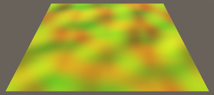
FlowMap
1
2
3
4
5
6
7
8
		void surf (Input IN, inout SurfaceOutputStandard o) {
			float2 flowVector = tex2D(_FlowMap, IN.uv_MainTex).rg;
			float2 uv = FlowUV(IN.uv_MainTex, _Time.y);
			fixed4 c = tex2D(_MainTex, uv) * _Color;
			o.Albedo = c.rgb;
			o.Albedo = float3(flowVector, 0);
			…
		}
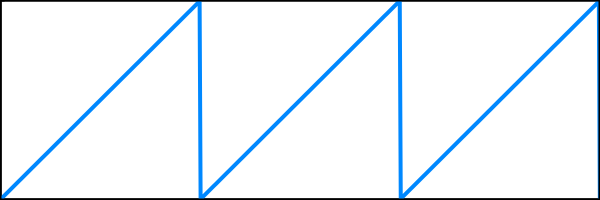
- To prevent it from turning into a mess, we have to reset the animation at some point. The simplest way to do this is by only using the fractional part of the time for the animation. Thus, it progresses from 0 up to 1 as normal, but then resets to 0, forming a sawtooth pattern.
1
2
3
4
float2 FlowUV (float2 uv, float2 flowVector, float time) {
	float progress = frac(time);
	return uv - flowVector * progress;
}
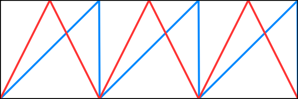
Seamless Looping
If we also start with black and fade in the texture at the start, then the sudden reset happens when the entire surface is black. While this is very obvious, at least there is no sudden visual discontinuity.
w(p)=1− 1−2p
Time Offset
It might be less obvious if we could spread it out over time. We can do this by offsetting the time by a varying amount across the surface.
1
2
3
4
			float2 flowVector = tex2D(_FlowMap, IN.uv_MainTex).rg * 2 - 1;
			float noise = tex2D(_FlowMap, IN.uv_MainTex).a;
			float time = _Time.y + noise;
			float3 uvw = FlowUVW(IN.uv_MainTex, flowVector, time);
Derivative Map
- A derivative map works just like a normal map, except it contains the height derivatives in the X and Y dimensions.
- averaging normals doesn’t make much sense
- the correct approach would be to convert the normal vectors to height derivatives, add them, and then convert back to a normal vector. This is especially true for waves that travel across a surface.
Looking Through Water
Transparent Surface Shader
- remove shadows
fillforwardshadows: we no longer need to support any shadow type.- remove
FallBack "Diffuse": This does not yet remove the shadows of the main directional light. Those are still added by the default diffuse shadow caster pass, which we’ve inherited from the diffuse fallback shader. To eliminate the shadows, remove the fallback.
1
Tags { "RenderType"="Transparent" "Queue"="Transparent" }
1
#pragma surface surf Standard alpha
Underwater Fog
_CameraDepthTexture: Unity makes the depth buffer globally available via the_CameraDepthTexturevariable- The underwater depth is found by subtracting the surface depth from the background depth. Let’s use that as our final color to see whether it is correct, scaled down so at least part of the gradient is visible.
1
2
3
4
5
6
7
8
9
10
11
12
13
14
15
16
 float3 ColorBelowWater (float4 screenPos) {
 	float2 uv = screenPos.xy / screenPos.w;

 	#if UNITY_UV_STARTS_AT_TOP
 		if (_CameraDepthTexture_TexelSize.y < 0) {
 			uv.y = 1 - uv.y;
 		}
 	#endif

 	float backgroundDepth =
 		LinearEyeDepth(SAMPLE_DEPTH_TEXTURE(_CameraDepthTexture, uv));
 	float surfaceDepth = UNITY_Z_0_FAR_FROM_CLIPSPACE(screenPos.z);
 	float depthDifference = backgroundDepth - surfaceDepth;

 	return depthDifference / 20;
 }
Grabbing the Background
To adjust the color of the background, we have to retrieve it somehow. The only way that’s possible with a surface shader is by adding a grab pass. This is done by adding GrabPass {} before the CGPROGRAM block in our shader.
1
GrabPass { "_WaterBackground" }
1
2
3
4
5
6
7
8
sampler2D _CameraDepthTexture, _WaterBackground;

float3 ColorBelowWater (float4 screenPos) {
	…

	float3 backgroundColor = tex2D(_WaterBackground, uv).rgb;
	return backgroundColor;
}
Applying Fog
1
2
3
4
5
6
7
8
9
10
float3 _WaterFogColor;
float _WaterFogDensity;

float3 ColorBelowWater (float4 screenPos) {
	…

	float3 backgroundColor = tex2D(_WaterBackground, uv).rgb;
	float fogFactor = exp2(-_WaterFogDensity * depthDifference);
	return lerp(_WaterFogColor, backgroundColor, fogFactor);
}
Fake Refraction
Because we already use screen-space data to create the underwater fog, we’ll reuse it for screen-space refractions. This allows us to add a refraction effect with little extra effort, although the result won’t be realistic.
Using the Normal Vector
1
2
3
4
float3 ColorBelowWater (float4 screenPos, float3 tangentSpaceNormal) {
	float2 uvOffset = tangentSpaceNormal.xy;
	…
}
Only Refract Underwater
- We can detect whether we’ve hit the foreground by checking whether the depth difference that we use for the fog is negative. If so, we’ve sampled a fragment that’s in front of the water
1
2
3
4
5
6
7
8
9
10
11
12
	float depthDifference = backgroundDepth - surfaceDepth;

	if (depthDifference < 0) {
		uv = screenPos.xy / screenPos.w;
		#if UNITY_UV_STARTS_AT_TOP
			if (_CameraDepthTexture_TexelSize.y < 0) {
				uv.y = 1 - uv.y;
			}
		#endif
	}

	float3 backgroundColor = tex2D(_WaterBackground, uv).rgb;
Static Lighting
Lightmapping: if both the lights and the geometry are unchanging, then we could calculate the lighting once and reuse it. This allows use to put many lights in our scenes, without having to render them at run time. It also makes it possible to use area lights, which are not available as realtime lights.
Flat and Wireframe Shading
Geometry Shaders
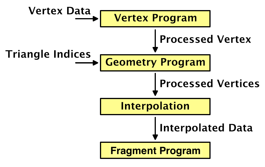 The added value of the — -
1
#pragma geometry MyGeometryProgram
Geometry shader is that the vertices are fed to it per primitive, so three for each triangle in our case. Whether mesh triangles share vertices doesn’t matter, because the geometry program outputs new vertex data. This allows us to derive the triangle’s normal vector and use it as the normal for all three vertices.
Geometry shaders are only supported when targeting shader model 4.0 or higher